INTEGRATED
SAMPLING SYSTEM
As it
is well known, the accuracy and reliability of process analyzers are
directly linked to the quality of the valves, manifolds, fittings and
various hardware used in the sampling system.
The best trace gas analyzer can’t have better performance than
the sampling system it is connected to.
In short, an analyzer is only as good as it’s sample system. By
many order of magnitude, today’s trace gas analyzers outperform the analyzers
designed 20 or 30 years ago and yet, it is not uncommon to find the same
sampling system design philosophy found 30 years ago.
For example, the quick connectors are still in use in many Air
Separation plants even with gas analyzers having ppb sensitivity.
As
a trace gas manufacturer, Contrôle Analytique reports that, more than
90% of its service calls are problems related to the sampling
system. It is obvious that
there is a need for a new approach concerning sample stream selection
systems and that this need is highly
addressed to the industrial gas industries.
The
Target
ü
Compact
design: - reduces enclosure and
housing costs;
ü
Leak
proof, Air diffusion resistant;
ü
No
sample stream cross contamination;
ü
Small
gas volume;
ü
No
dead or unswepted dead volume:
- eliminates virtual leaks
- reduces dry-down and purge time
ü
Ease
of operation; micro
processor, intelligent support
ü
Easy
integration to an automatic process as remote control or automatic
sample selection, calibration or truck loading operations;
ü
Possibility
of serial communication with remote computer, PLC or DCS.
The
Solution
The
Conventional Way
Ø
Engineering
department must select all hardware, i.e. valves, tubing, etc.
Ø
Purchasing
department must give assembly contract to a panel builder.
Ø
Panel
certification shipping, on site installation and start-up.
The
conventional way requires the implication of many people from the
engineering department, the purchasing and third party contractors.
It is very expensive and prones to communication errors.
This type of system is bulky and the performances are variable.
Our
Way
Ø
One
stop buy;
Ø
Engineering
specifies how many inputs/outputs;
Ø
Purchasing
department issues one purchase order for a complete system;
Ø
Systems
are built, tested and shipped ready to use.
Ø
No
headaches. Plug and Play
philosophy;
Ø
Replaces
complete sample panel, discrete valving system with one small 5 inch high
rack mounted cabinet.
The
Concept
In
figure 1, the SV valves are miniature, low internal volume, manifold
mounted two way sample selection valves.
The FV valves and associated FT flow transducers are used as bypass
“electronic rotometers”. Each
inlet has its own 2 micron particle filter.
The FT-V flow transducer, monitors the outlet backpurge flow.
In
figure 1, sample #1 is selected, so SV-1 is open and SV-2 to SV-n are
closed. On each respective
sample inlet, there is a bypass flow that is
maintained by the microprocessor at the entered bypass flow set
point. So each FV bypass flow control valve maintains the bypass
flow at their respective set point. The
unselected sample stream valves have their discharge side backpurged
with the gas coming from the selected stream.
The backpurge flow is limited by its respective flow restrictor
“R”. This eliminates any
unswept dead volume and speeds up upset recovery.
The
output stabilisation loop allows a smooth, equilibrated flow and no dead
volume. Finally, an optional
electronic back pressure regulator may be installed to maintain outlet
pressure constant.
The
Design
Practically
all SV valves are mounted on a stainless steel manifold.
All gas inlets and outlets are welded on the manifold’s body.
Finally the manifold, holding the selection
SV valves, is mounted in a box that can be purged or maintained
under vacuum, based on application. This
eliminates completely the possibility of air diffusion into the system.
All other parts of the system like the inlet bypass flow control
valves and associated flow transducers are mounted outside of the purged
box. These parts are not
critical for the sample contamination.
Designed
to FIT
Each
system may be tailor made to fit the final application.
The number of sample inlets or outlets, the number of systems in a
cabinet, etc…
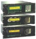
Embedded
Software
The
software controls all the system operations.
The user interface is done through 4x4 keypad and 4x40 LCD display.
Upon power up, the user is prompted for inlet stream bypass flow
set point. Optionally, the
user enters back pressure set point if the system is equipped with an
electronic back pressure regulator.
The
user also enters identification tags for sample inlet.
The stream (or tag) to be sampled is selected by pressing the
associate number on the keypad. Automatic
sample stream sequencing can be configured.
The back purge flow is also displayed.
The software will issue an alarm when there is not enough flow
(pressure) from a sample stream inlet.
An appropriate digital dry contact output will be activated.
The software makes sure to close a valve before opening a newly
selected one to avoid cross flow. The
system has an isolated RS-232C communication port for interface with PLC,
DCS, computer, etc…
|
Specifications |
|
| Number of
sample inlets: |
User defined, up to 16.
Special configurations on request |
| Bypass flow
range: |
0 to 5 liter/min, resolution 1
cc/mm |
| Back purge
flow: |
0 to 200 cc/min |
| Gas
connections: |
-
1/8”, 1/4” or 3,4 or 6 mm.
- Double ferrules Swagelock® type
- Stainless steel compression fittings
|
| Power: |
115
VAC or 220 VAC, 50/60
Hz
Maximum 50 watts |
| Valve
rated life: |
Minimum
500,000 actuation. |
| Usable
gas: |
N2,
He, Ar, O2, H2, CO2, CH4,
non condensable HC.
-All noble gases
-No corrosive gases. |
| Standard
features: |
-
Isolated RS-232C serial port with simple ASCII protocol
- Dry contact alarm outputs
-
User programmable time based sample stream sequencing or calibration
sequence
- Electronic sample inlets bypass flow controller
- Outlet backpurge
flow
- Fully microprocessor controlled with 4 x 40 LCD
display
- Self-diagnostic system software
- Purged valve
enclosure
- Oxygen cleaned
and compatible
|
| Option:
|
-Electronic backpressure
regulator to maintain constant outlet pressure. |
Specifications
may change without notice.
|